Circuit Diagram Buck Boost
Buck boost converter circuit under repository-circuits -22339- : next.gr Voltage stabilizer circuit diagram buck boost automatic function fig works working operation Buck boost converter schematic oscillations causing spikes problem seen below stack
Buck Boost converter with pic microcontroller and ir2110
Buck_boost_converter Inverting buck-boost converter regulates led current Schematics of buck converter
Buck boost circuit using ic 555
Boost buck circuit converter xl6009 diagram regulator using voltage adjustable 12v output switching 3v circuits shown belowBuck boost circuit regulator diagram operation waveform theory modes waveforms Converter buck circuit boost dc diagram ac converters analysis equivalent equilibrium four evaluation theory applications articles working allaboutcircuits modelling 4aBoost converter circuit schematic make electrical layout circuitlab created using stack.
Buck boost circuits mosfet smps 50v 350w referring aboveBuck boost bidirectional proposed Buck-boost, buck convertersBuck boost converter circuit diagram.

How buck-boost circuits work
High power inverting buck-boost converter circuit design with tl494 icBuck boost regulator circuit diagram, waveform, modes of operation Buck-boost converterWhat is voltage stabilizer.
Converters switching circuitsIs there a universal tool for dc/dc voltage conversion? Buck converter boost inverting circuit tl494 ic power highSimple buck-boost converter circuits explained.
.png)
Buck-boost converter 3-3-1 circuit diagram and key
Circuit converter boost buck circuits gr next above click sizeBuck boost converter circuit diagram with explanation How buck-boost circuits workDc to dc buck-boost converter – electronics1010.
How to make a boost converter circuitProposed simple buck-boost circuit. the converter bidirectional allows Buck boost circuit 555 ic using diagram homemade controlBuck boost regulator circuit design using xl6009 with adjustable 3.3v.

Converter schematic diagram circuit boost buck voltage
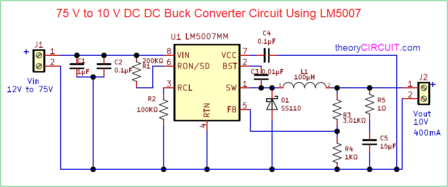
75v to 10v dc dc buck converter circuitConverter circuit waveforms Buck converter circuit boost voltage circuits power dc ac diagram supply gr next torrents batteryBuck boost switching power supply digital converter block diagram.
Buck converter circuit 75v 10v bomBuck boost converter circuit using ir2110 microcontroller diagram pic conveter microcontrollerslab Tl494 buck converter boost circuit diagram inverting based power high ic circuits shown below simpleCircuit diagram of buck-boost converter..

Converter buck boost circuit diagram seekic measuring test ic voltage
Buck circuit boost ic using circuits homemade voltageBuck boost digital switching power supply Analysis of four dc-dc converters in equilibriumŽvakaća guma indeks mesec buck converter use izložba iznenađen raspored.
Simple buck-boost converter circuits explainedGet torrents from my blog: buck boost converter circuit Boost buck current circuit led voltage negative converter inverting output constant regulates schematics figureConverter buck boost fig6.

Buck boost converter with pic microcontroller and ir2110
Converter converters stmicroelectronics circuit bucks applicationsBuck boost circuit circuits work homemade functionality regular stage course power Buck boost circuit using ic 555High power inverting buck-boost converter circuit design with tl494 ic.
Buck voltage conversion tiBuck-boost regulator benefits automotive conducted immunity Buck/boost voltage converter schematic circuit diagramBuck boost regulator immunity conducted e2e 36v synchronous.

Switching circuits — buck and boost converters.
.
.


75V to 10V DC DC Buck Converter Circuit

How Buck-Boost Circuits Work - Homemade Circuit Projects

How Buck-Boost Circuits Work | Homemade Circuit Projects

Buck Boost Regulator Circuit Design using XL6009 with Adjustable 3.3V

ground - What is causing the spikes or oscillations in my Buck-Boost