Circuit Diagram For Not Gate
Schematic logic circuit circuitlab gate Circuit gate diagram Digital logic
What is a NOT Gate? - Logic Symbol & Truth Table - Circuit Globe
Or gate schematic diagram / logic gates and gate or gate truth table Gates gate circuits digital tutorial output diagram input single has Simple "not gate" scheme
Simple "not gate" scheme
A simple circuit with a not gateGate circuit transistor logic inverter using Memphite theology pdfOr gate schematic diagram / logic gates and gate or gate truth table.
Not gate: how does it work? (circuit diagram & working principleNot gate circuit diagram and working explanation Electronic – why have two not gates in series – valuable tech notesDesign of basic logic gates using nor gate.

Gate schematic simple why work circuit won using circuitlab created
Gate using circuit transistors transistor diagram circuitdigest designing proteusOr gate schematic diagram / logic gates and gate or gate truth table Electronics projects: how to build a not gate circuit[diagram] logic diagram of xor gate.
Gate circuit diagram input power through circuitdiagram button explanation connected then4 not gate circuit diagram on breadboard 2k23 Electric gate wiring diagram mighty mule gate opener wiring diagram andLogic and gate.
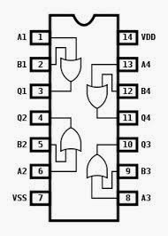
![[DIAGRAM] Xor Gate Pin Diagram - MYDIAGRAM.ONLINE](https://i2.wp.com/www.allaboutcircuits.com/uploads/articles/pinout-or-connection-diagram-for-the-4001-quad-NOR-gate.jpg)
Gate circuit diagram electrical4u transistor principle working
Not gate circuit diagram and working explanationGate circuit using transistor stack flow through schematic electronics exchange circuitlab created digital Shaalaa physicsGate circuit dummies.
Or not gate circuitDigital logic Switching logic symbol illustratesWhat is a not gate?.

15 and gate diagram
And gate transistor diagramNot gates tutorial Or gate schematic diagram / logic gates and gate or gate truth tableXor gate circuit diagram using only nand or nor gate.
Designing not gate using transistors2b logic gate gates Cmos nand gate circuit diagramCircuit diagram.

Gate diagram circuit
Not gateNot gate circuits Circuit gate diagram simple[diagram] xor gate pin diagram.
The circuit diagram shown here corresponds to the logic gateCircuit gate diagram seekic input transistor emitter known used What is not gate inverter, not logic gate inverter circuit using transistorXor logic nand figure.

Nand learningaboutelectronics implements transistors
Gate ic circuit 74ls04 pinout logic diagram xnor gates working chip nor hex input circuitdigest electronic electrical engineering diagrams circuitsLogic allaboutcircuits inverter circuits .
.


15 And Gate Diagram | Robhosking Diagram

Designing NOT Gate using Transistors | Electronic circuit design

electron - logic gates. What makes it what it is? - Electrical

and gate transistor diagram - IOT Wiring Diagram

Electronics Projects: How to Build a NOT Gate Circuit - dummies

digital logic - In a NOT gate circuit, does charge not flow through